DIY Audio Circuits Circuit Diagram Learn how to use the Digital Multimeter with detailed documentation, including pinouts, usage guides, and example projects. Perfect for students, hobbyists, and developers integrating the Digital Multimeter into their circuits.
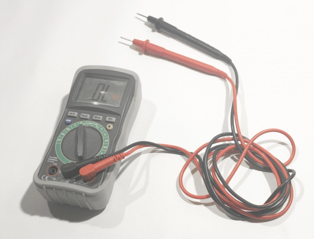
This document provides an overview of the typical design of a modern digital multimeter. It discusses the main components, including input protection, a range selection switch, signal conditioning circuitry, an analog-to-digital converter (ADC), a microcontroller, and an LCD display. The document then examines each measurement range in more detail, explaining how the circuitry is configured
Digital Multimeter with Arduino (Measure Voltage, Resistance and Diode) Circuit Diagram
Project Overview In this project, you will construct a simple analog multimeter. illustrated in Figure 1, which supports both voltage and current measurements. Figure 1. Illustration of the analog multimeter built in this project. Parts and Materials Sensitive meter movement Selector switch, single-pole, multi-throw, break-before-make Multi-turn potentiometers, PCB mount. 15-turn, 1 kΩ, and
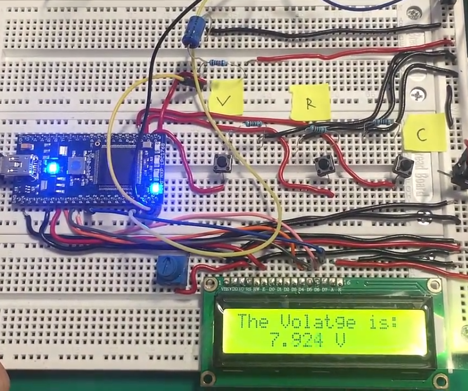
Learn how to build a precise voltmeter and ohmmeter using the digitalRead function of an Arduino with step-by-step instructions and pictures. A multimeter is a must-have tool in your arsenal when it comes to creating or developing electrical circuits. Without it, executing a job will be extremely tough. So, in this post, we chose to create a low-cost digital multimeter using Arduino and other basic components. DIY Arduino Multimeter EE Makers 2 notes 2 notes Jan 25th, 2023 kalifissure

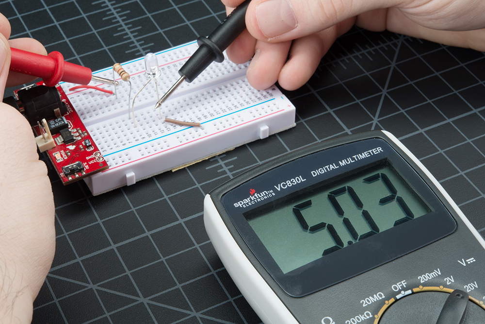
Electronic Components Testing (Step by Step Guide, 2025) Circuit Diagram
In this article, we try to explain the electronic components testing process in an easy to understand step by step guide. A multimeter is a must-have tool in your arsenal when it comes to creating or developing electrical circuits. Without it, executing a job will be extremely tough. So, in this post, we chose to create a low-cost digital multimeter using Arduino and other basic components. When it comes to the multimeter's functions, it can measure voltage up to 24V, as well as diode, resistance, and voltage

Learn how to build a cost-effective digital multimeter using Arduino. Measure voltage, current, resistance, and capacitance with this step-by-step guide.
